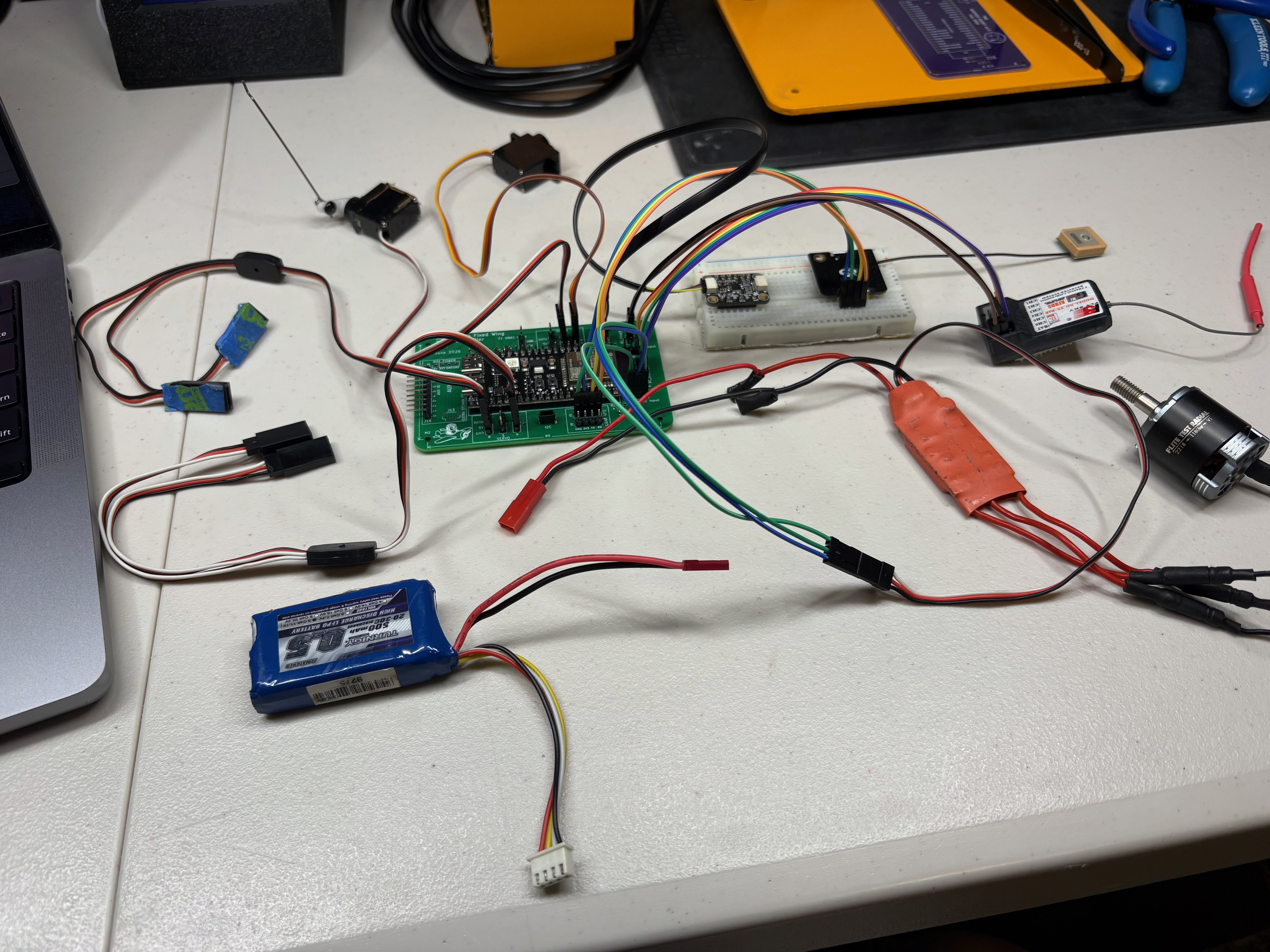
breadboard
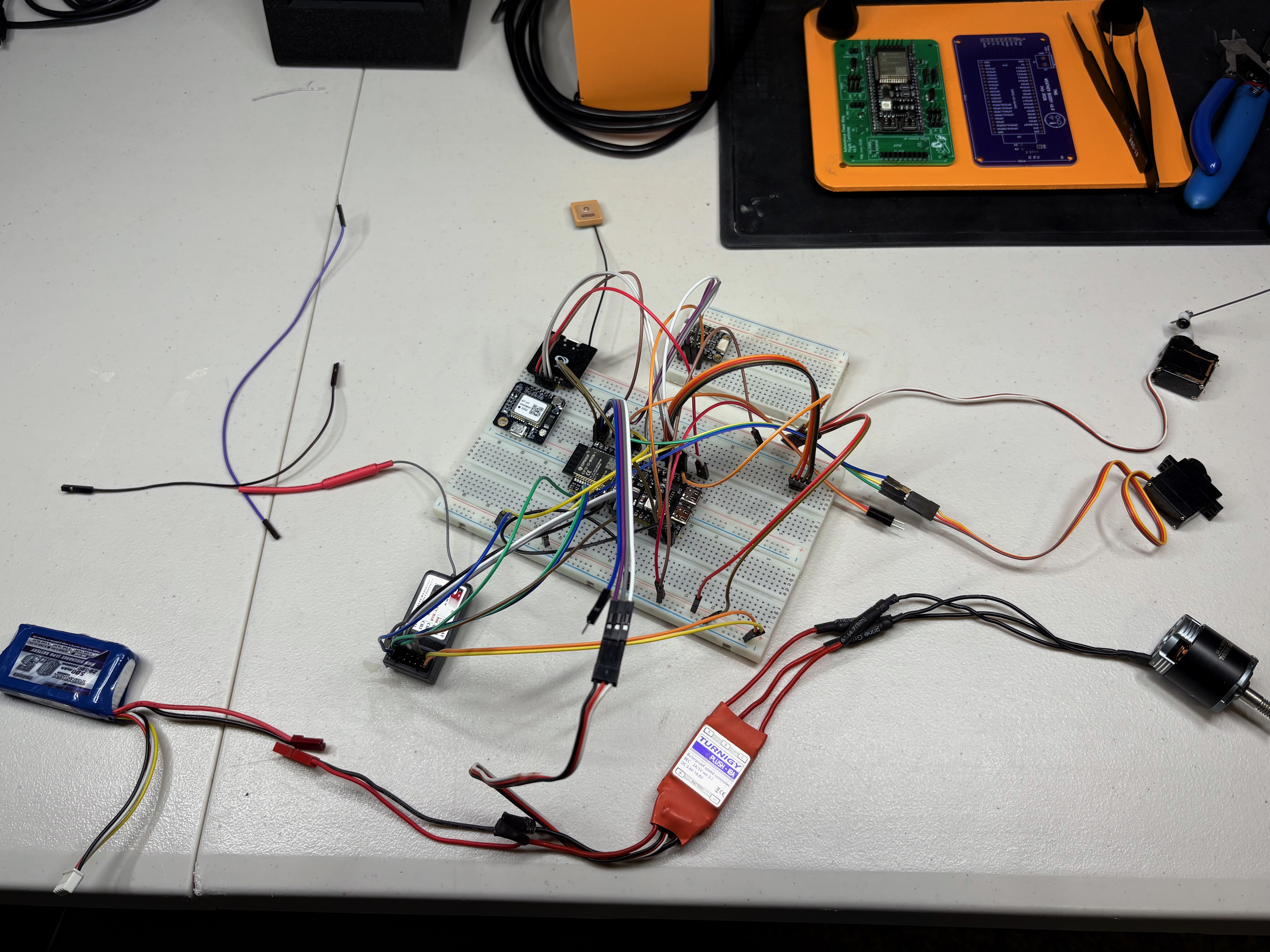
bench prototypeESP32-S3 devkit and standalone sensor modules on a breadboard. Proved out the sensor drivers, RC pulse capture, PWM outputs, and the first control loop before moving to a real board.
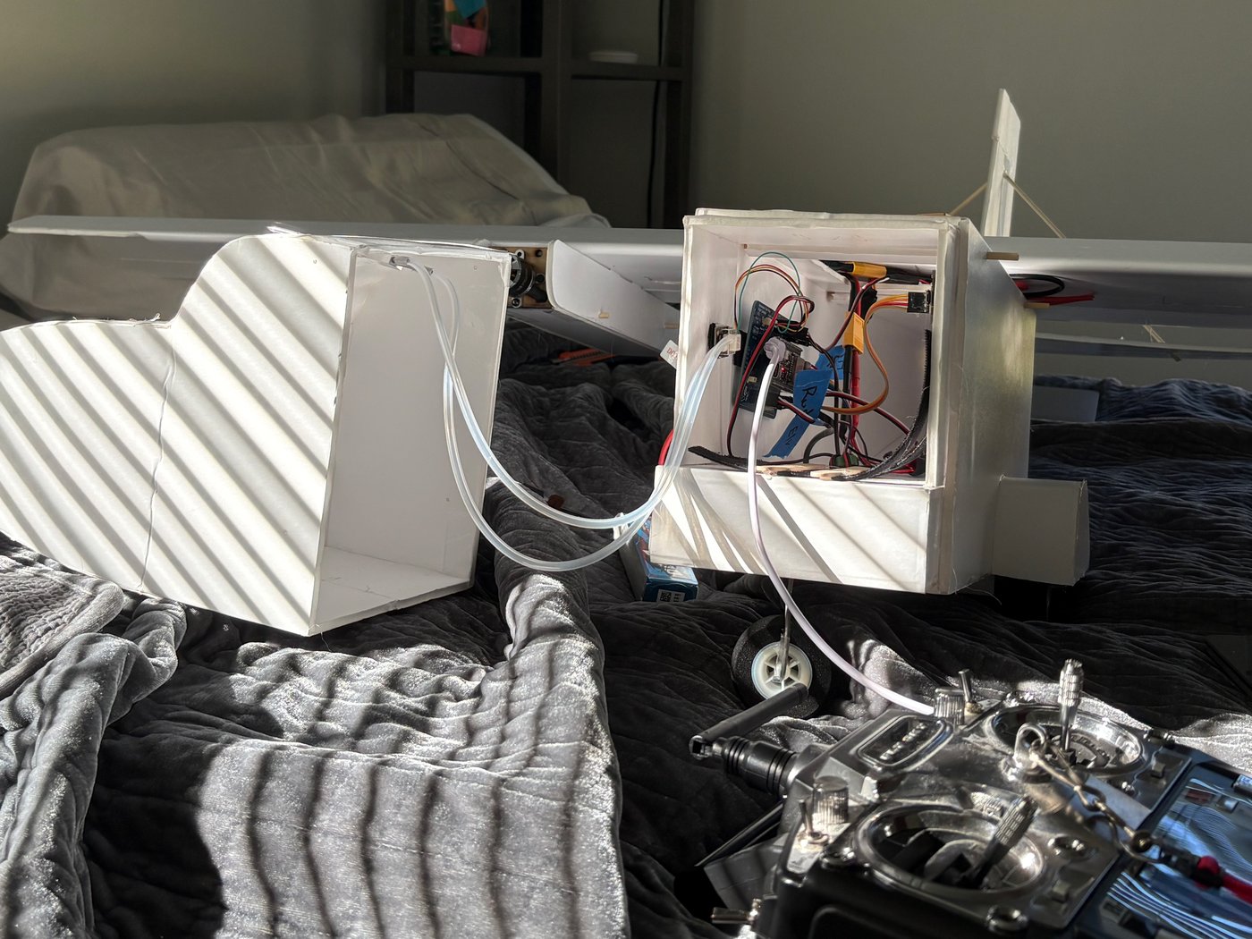
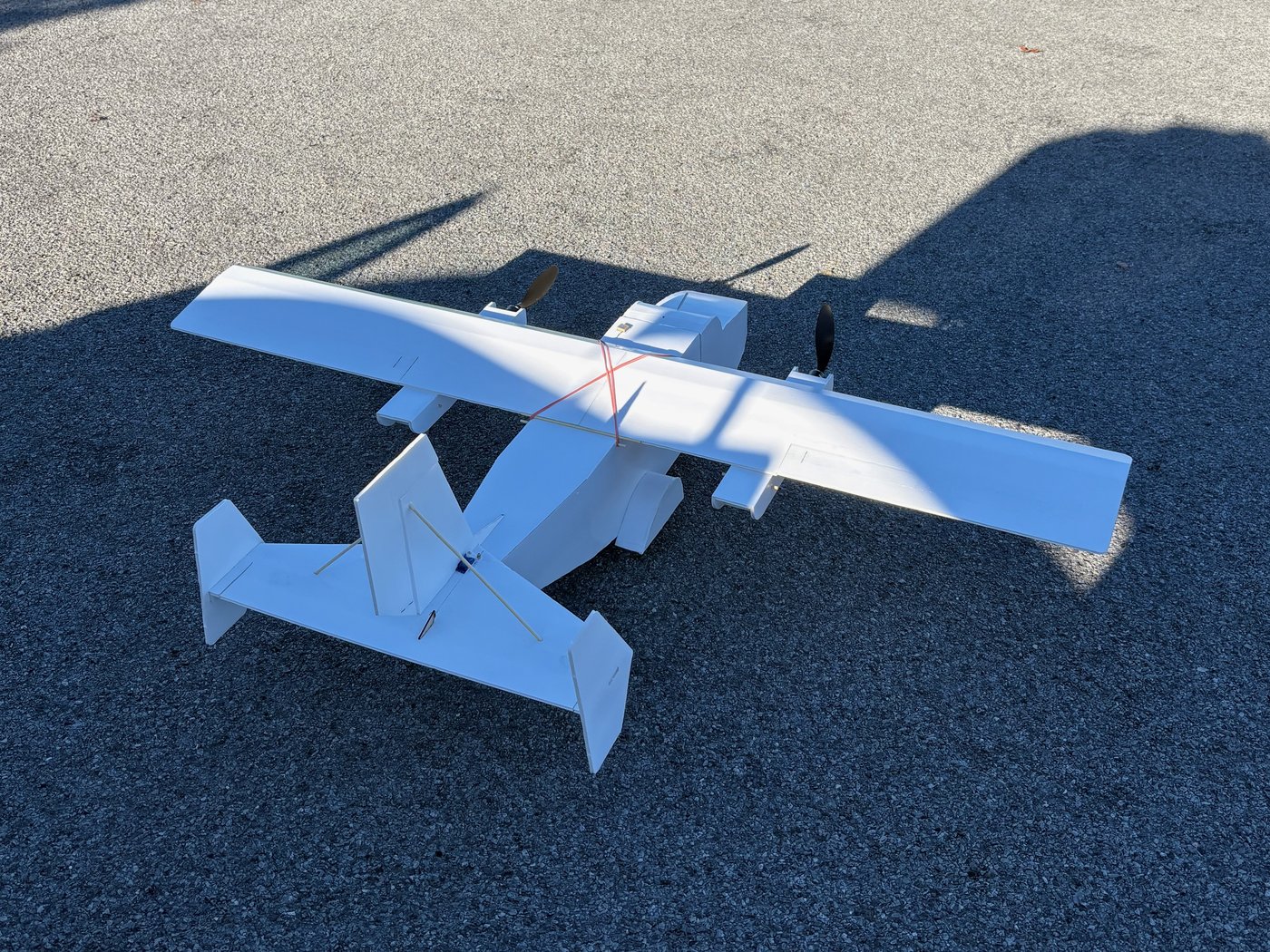
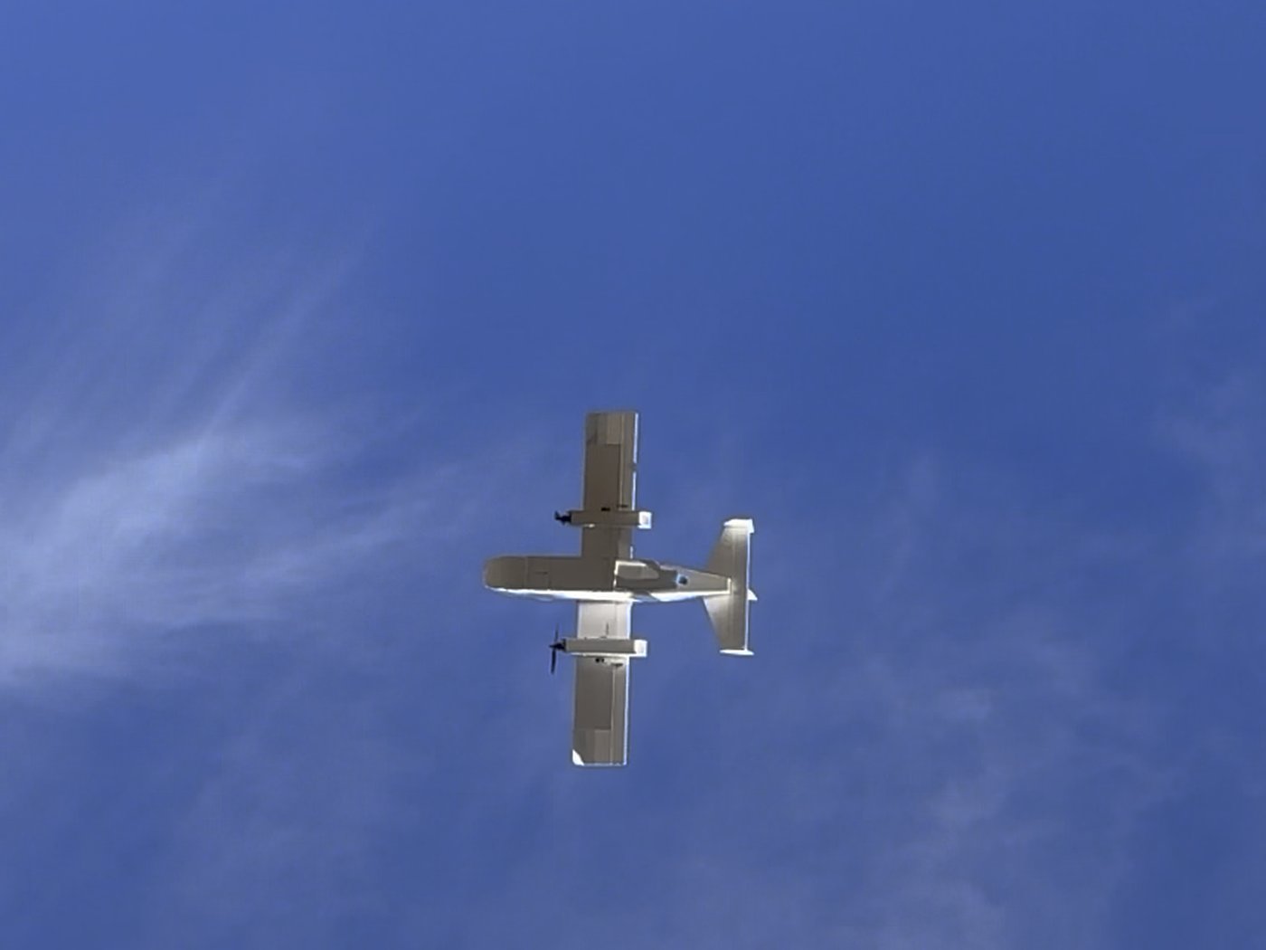
My roommate and I are building an autonomous fixed-wing RC plane from scratch. He's a mechanical engineer who designed and built the airframe and control surfaces, picked the motors and servos, and mounted everything in the plane. I designed the flight controller, which is all of the electronics and all of the software. It sits between a standard RC receiver and the plane's servos and ESCs. In manual mode it passes the pilot's commands straight through, and when the pilot flips a switch it takes over, holding attitude with PID loops and steering toward GPS waypoints.
ESP32-S3 devkit and standalone sensor modules on a breadboard. Proved out the sensor drivers, RC pulse capture, PWM outputs, and the first control loop before moving to a real board.
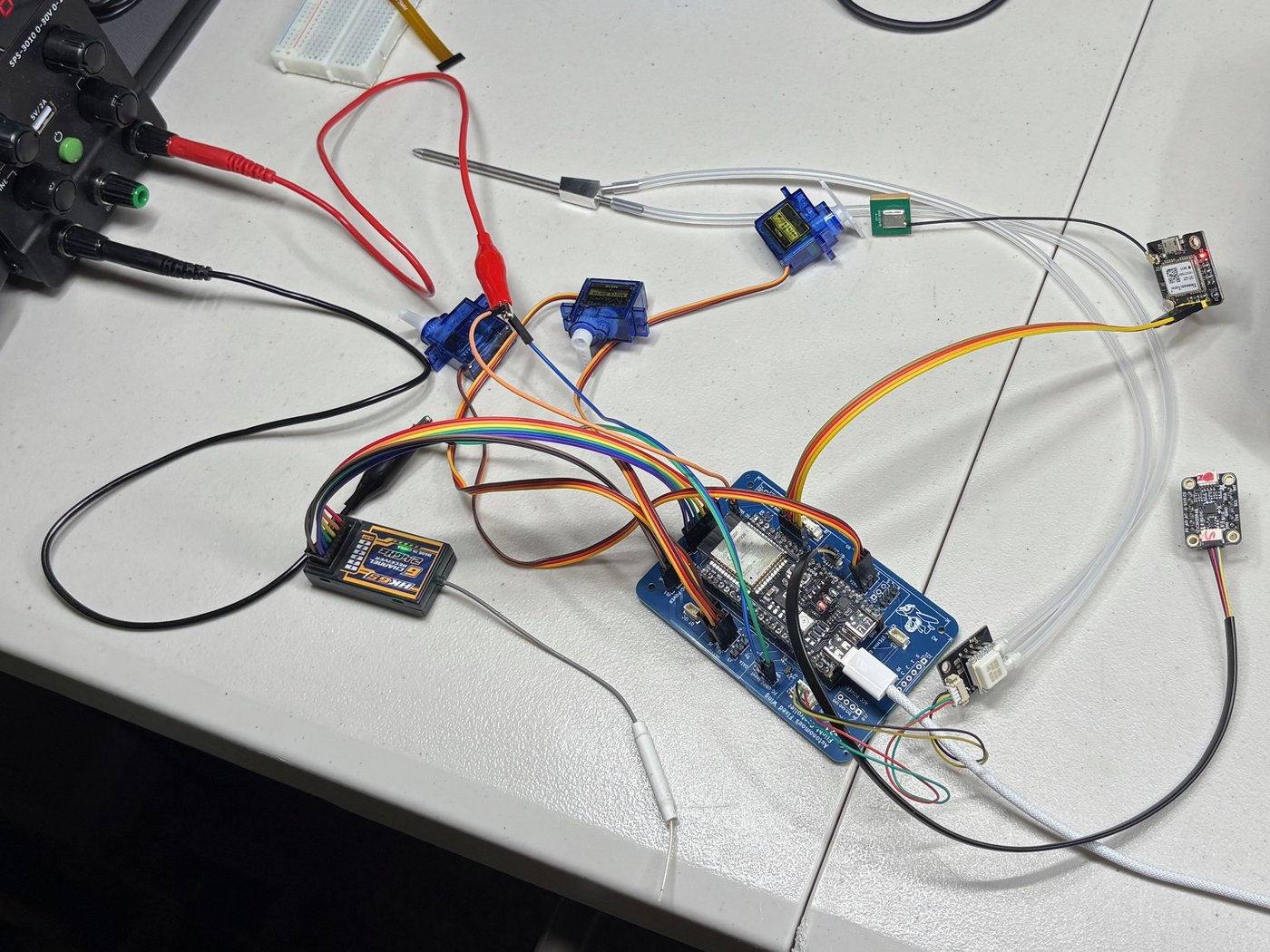
My first PCB: a carrier board for the ESP32-S3 devkit with nearly the same layout v2 ended up with, moving the breadboard wiring onto real connectors for the servos, ESCs, receiver, and sensors.
Bringing it up turned up a few mistakes. Some connectors had TX and RX swapped, so I bridged them with jumper wires. The airspeed sensor had the wrong connector and only got 3.3V instead of the 5V it needs. Some RC inputs landed on pins that aren't usable on my devkit, and a few silkscreen labels were misprinted. v2 fixed all of it.
Carrier board for the ESP32-S3 devkit. Routes the receiver, 6 servo and 2 ESC outputs, and the off-board IMU, GPS, and pitot airspeed sensor to proper connectors.
Splits power into isolated servo and logic rails, so a stalling servo can't brown out the flight controller.
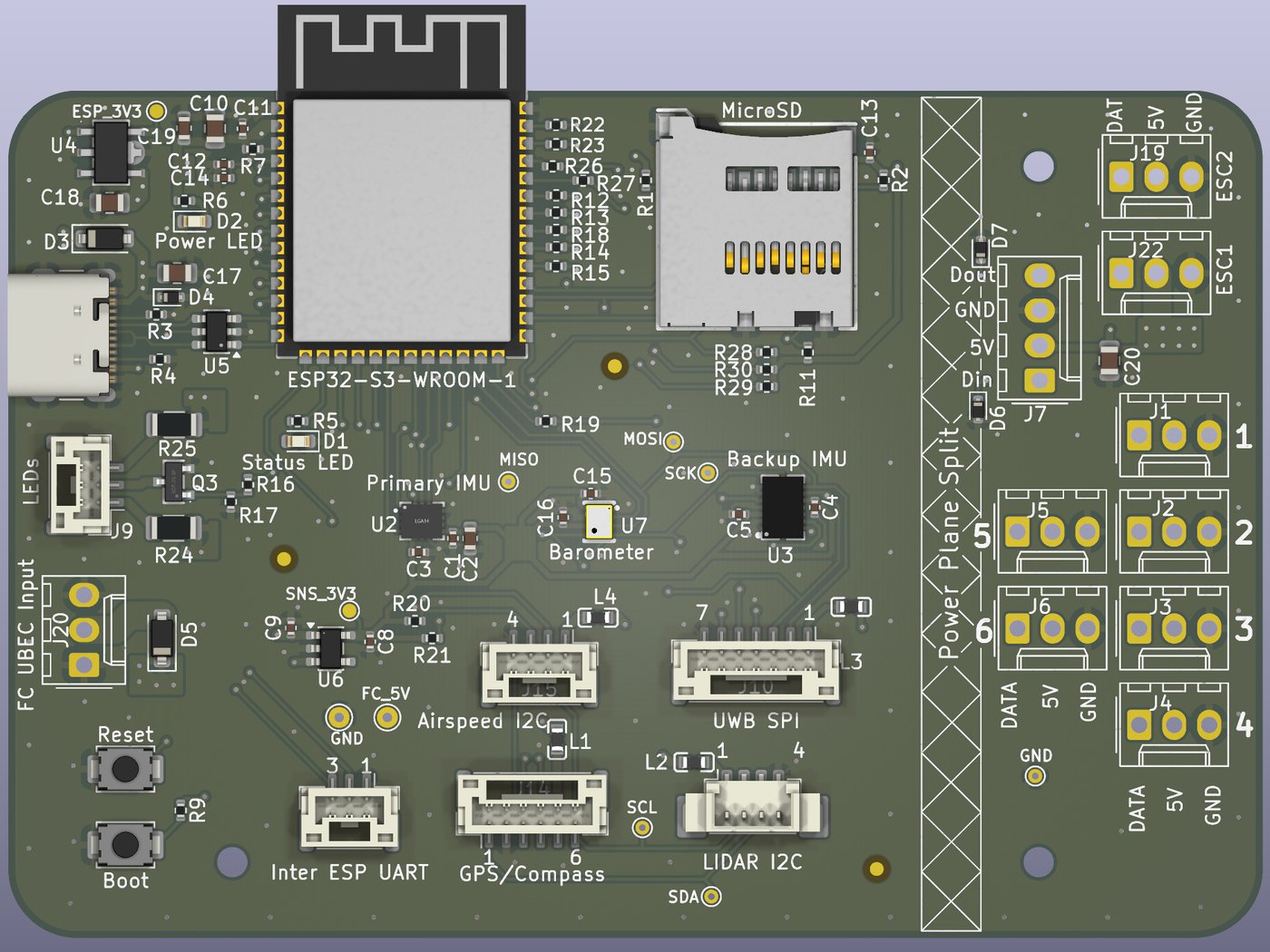
Fully custom board. Primary and backup IMUs onboard over SPI from different manufacturers (ICM-42688-P and BMI088), a DPS368 barometer for altitude, and microSD logging.
Heading moves to an external compass mounted away from the motor and power wiring, and the RC input becomes a serial line for a digital receiver.